配置IPv4三层组播over M-LAG示例
组网需求
如图4-31所示,IPv4网络中,为了保证网络的高可靠性,用户侧二层交换机Switch通过M-LAG双归接入到双活VRRP网关SwitchA和SwitchB。连接在二层交换机Switch上的用户Receiver希望通过组播方式接收来自Source的视频节目。
图4-31 配置IPv4三层组播over M-LAG组网图
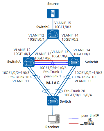
表4-37 组网图信息表
| 设备 | 接口 | VLANIF接口 | IP地址 | |
|---|---|---|---|---|
| SwitchA | 10GE1/0/1 | VLANIF 12 | 10.3.1.1/24 | |
| SwitchA | 10GE1/0/6 | VLANIF 13 | 10.5.1.1/24 | |
| SwitchA | Eth-Trunk 10 | VLANIF 11 | 10.2.1.1/24 | |
| SwitchA | MEth0/0/0 | – | 10.1.1.1/24 | |
| SwitchB | 10GE1/0/1 | VLANIF 14 | 10.4.1.1/24 | |
| SwitchB | 10GE1/0/6 | VLANIF 13 | 10.5.1.2/24 | |
| SwitchB | Eth-Trunk 10 | VLANIF 11 | 10.2.1.2/24 | |
| SwitchB | MEth0/0/0 | – | 10.1.1.2/24 | |
| SwitchC | 10GE1/0/1 | VLANIF 12 | 10.3.1.2/24 | |
| SwitchC | 10GE1/0/2 | VLANIF 14 | 10.4.1.2/24 | |
| SwitchC | 10GE1/0/3 | VLANIF 15 | 10.6.1.1/24 |
配置思路

要实现以上需求,需要保证M-LAG主备设备(SwitchA和SwitchB)之间除了peer-link链路外,还有直连的三层链路,同时要求M-LAG主备设备上的组播配置保持一致。
可按照以下思路进行配置:
- 在SwitchA和SwitchB上配置M-LAG和VRRP,并在Switch上配置双归接入,保证网络的高可靠性。
- 在SwitchA、SwitchB和SwitchC上配置单播路由协议,实现网络层互通。单播路由正常是组播路由协议正常工作的基础。
- 在SwitchA和SwitchB的VLANIF接口上配置PIM-SM和IGMP,在SwitchC的VLANIF接口上配置PIM-SM,实现组播转发表项的建立。
- 在SwitchA和SwitchB的用户侧VLANIF接口上使能PIM Silent,保证SwitchA和SwitchB均作为DR,并均向RP发送Join报文。
- 在SwitchA和SwitchB上VLANIF接口对应的VLAN内使能IGMP Snooping,实现组播数据在二层网络的精确转发。
- 为了保证组播数据在M-LAG中的正常转发,需要在连接M-LAG主备设备的三层链路的接口上关闭STP,并在peer-link链路上配置不允许通过的VLAN。
操作步骤
配置基于V-STP的M-LAG和VRRP。
配置基于V-STP的M-LAG
# 在SwitchA上配置基于V-STP的M-LAG,包括配置DFS Group、peer-link、V-STP、M-LAG接口、LACP M-LAG的系统优先级和系统ID。SwitchB的配置与SwitchA相似,配置过程略,详见配置文件。
system-view
[~HUAWEI] sysname SwitchA
[*HUAWEI] commit
[~SwitchA] interface meth 0/0/0
[~SwitchA-MEth0/0/0] ip address 10.1.1.1 24
[*SwitchA-MEth0/0/0] quit
[*SwitchA] dfs-group 1
[*SwitchA-dfs-group-1] source ip 10.1.1.1
[*SwitchA-dfs-group-1] priority 150
[*SwitchA-dfs-group-1] quit
[*SwitchA] interface eth-trunk 1
[*SwitchA-Eth-Trunk1] trunkport 10ge 1/0/4 to 1/0/5
[*SwitchA-Eth-Trunk1] mode lacp-static
[*SwitchA-Eth-Trunk1] peer-link 1
[*SwitchA-Eth-Trunk1] quit
[*SwitchA] stp mode rstp
[*SwitchA] stp v-stp enable
[*SwitchA] vlan batch 11
[*SwitchA] interface eth-trunk 10
[*SwitchA-Eth-Trunk10] mode lacp-static
[*SwitchA-Eth-Trunk10] port link-type trunk
[*SwitchA-Eth-Trunk10] port trunk allow-pass vlan 11
[*SwitchA-Eth-Trunk10] trunkport 10ge 1/0/2 to 1/0/3
[*SwitchA-Eth-Trunk10] dfs-group 1 m-lag 1
[*SwitchA-Eth-Trunk10] lacp m-lag priority 10
[*SwitchA-Eth-Trunk10] lacp m-lag system-id 00e0-fc00-0000
[*SwitchA-Eth-Trunk10] quit
[*SwitchA] commit
# 在Switch上配置上行接口绑定在一个Eth-Trunk中。
system-view
[~HUAWEI] sysname Switch
[*HUAWEI] commit
[~Switch] vlan batch 11
[*Switch] interface eth-trunk 20
[*Switch-Eth-Trunk20] mode lacp-static
[*Switch-Eth-Trunk20] port link-type trunk
[*Switch-Eth-Trunk20] port trunk allow-pass vlan 11
[*Switch-Eth-Trunk20] trunkport 10ge 1/0/1 to 1/0/4
[*Switch-Eth-Trunk20] quit
[*Switch] commit
配置VRRP
# 在SwitchA上配置VRRP备份组。SwitchB的配置与SwitchA相似,配置过程略,详见配置文件。此处VRRP工作在双主状态,两端的VRID和虚拟IP配置要求完全一致,目的是为M-LAG提供相同的虚拟IP和虚拟MAC。
[~SwitchA] interface vlanif 11
[*SwitchA-Vlanif11] ip address 10.2.1.1 24
[*SwitchA-Vlanif11] vrrp vrid 1 virtual-ip 10.2.1.111
[*SwitchA-Vlanif11] quit
[*SwitchA] commit
配置OSPF功能,实现网络层互通。
# 配置SwitchA。SwitchB和SwitchC的配置与SwitchA相似,配置过程略,详见配置文件。
[~SwitchA] vlan batch 12 13
[*SwitchA] interface 10ge 1/0/1
[*SwitchA-10GE1/0/1] port link-type trunk
[*SwitchA-10GE1/0/1] port trunk allow-pass vlan 12
[*SwitchA-10GE1/0/1] quit
[*SwitchA] interface 10ge 1/0/6
[*SwitchA-10GE1/0/6] port link-type trunk
[*SwitchA-10GE1/0/6] port trunk allow-pass vlan 13
[*SwitchA-10GE1/0/6] quit
[*SwitchA] interface vlanif 12
[*SwitchA-Vlanif12] ip address 10.3.1.1 24
[*SwitchA-Vlanif12] quit
[*SwitchA] interface vlanif 13
[*SwitchA-Vlanif13] ip address 10.5.1.1 24
[*SwitchA-Vlanif13] quit
[*SwitchA] ospf 1
[*SwitchA-ospf-1] area 0
[*SwitchA-ospf-1-area-0.0.0.0] network 10.1.1.1 0.0.0.255
[*SwitchA-ospf-1-area-0.0.0.0] network 10.3.1.0 0.0.0.255
[*SwitchA-ospf-1-area-0.0.0.0] network 10.5.1.0 0.0.0.255
[*SwitchA-ospf-1-area-0.0.0.0] quit
[*SwitchA-ospf-1] quit
[*SwitchA] commit
如果单播路由选路时peer-link链路被选为到达RP或组播源的最优链路,可能会导致出接口为peer-link接口的组播流量不通。为了避免此问题,需要保证M-LAG主备设备之间的三层链路的路由开销值小于或等于peer-link链路的路由开销值,使得单播路由选路时选择到M-LAG主备设备之间的三层链路。
在SwitchA和SwitchB的VLANIF接口上配置PIM-SM和IGMP,在SwitchC的VLANIF接口上配置PIM-SM。
# 配置SwitchA。SwitchB的配置与SwitchA相似,配置过程略,详见配置文件。
[~SwitchA] multicast routing-enable
[*SwitchA] interface vlanif 11
[*SwitchA-Vlanif11] pim sm
[*SwitchA-Vlanif11] igmp enable
[*SwitchA-Vlanif11] quit
[*SwitchA] interface vlanif 12
[*SwitchA-Vlanif12] pim sm
[*SwitchA-Vlanif12] igmp enable
[*SwitchA-Vlanif12] quit
[*SwitchA] interface vlanif 13
[*SwitchA-Vlanif13] pim sm
[*SwitchA-Vlanif13] igmp enable
[*SwitchA-Vlanif13] quit
[*SwitchA] commit
# 配置SwitchC。将SwitchC上的VLANIF 15接口指定为C-BSR和C-RP。
[~SwitchC] multicast routing-enable
[*SwitchC] interface vlanif 12
[*SwitchC-Vlanif12] pim sm
[*SwitchC-Vlanif12] quit
[*SwitchC] interface vlanif 14
[*SwitchC-Vlanif14] pim sm
[*SwitchC-Vlanif14] quit
[*SwitchC] interface vlanif 15
[*SwitchC-Vlanif15] pim sm
[*SwitchC-Vlanif15] quit
[*SwitchC] pim
[*SwitchC-pim] c-bsr vlanif 15
[*SwitchC-pim] c-rp vlanif 15
[*SwitchC-pim] quit
[*SwitchC] commit
在SwitchA和SwitchB的用户侧VLANIF接口上使能PIM Silent。
# 配置SwitchA。SwitchB的配置与SwitchA相似,配置过程略,详见配置文件。
[~SwitchA] interface vlanif 11
[~SwitchA-Vlanif11] pim silent
[*SwitchA-Vlanif11] quit
[*SwitchA] commit
在SwitchA和SwitchB上VLANIF接口对应的VLAN内使能IGMP Snooping。
# 配置SwitchA。SwitchB的配置与SwitchA相似,配置过程略,详见配置文件。
[~SwitchA] igmp snooping enable
[*SwitchA] vlan 11
[*SwitchA-vlan11] igmp snooping enable
[*SwitchA-vlan11] quit
[*SwitchA] vlan 12
[*SwitchA-vlan12] igmp snooping enable
[*SwitchA-vlan12] quit
[*SwitchA] vlan 13
[*SwitchA-vlan13] igmp snooping enable
[*SwitchA-vlan13] quit
[*SwitchA] commit
在连接M-LAG主备设备的三层链路的接口上关闭STP,并在peer-link链路上配置不允许通过的VLAN。
# 配置SwitchA。SwitchB的配置与SwitchA相似,配置过程略,详见配置文件。
[~SwitchA] interface 10ge 1/0/6
[~SwitchA-10GE1/0/6] stp disable
[*SwitchA-10GE1/0/6] quit
[*SwitchA] interface eth-trunk 1
[*SwitchA-Eth-Trunk1] port vlan exclude 1 13
[*SwitchA-Eth-Trunk1] quit
[*SwitchA] commit
验证配置结果。
# 在SwitchA上执行命令display dfs-group,查看M-LAG的相关信息。
[~SwitchA] display dfs-group 1 m-lag
*                : Local node
Heart beat state : OK
Node 1 *
 Dfs-Group ID   : 1
 Priority       : 150
 Address        : ip address 10.1.1.1
 State          : Master
 Causation      : -
 System ID      : 0025-9e95-7c31
 SysName        : SwitchA
 Version        : V200R003C00SPC200
 Device Type    : CE6850EI
Node 2
 Dfs-Group ID   : 1
 Priority       : 120
 Address        : ip address 10.1.1.2
 State          : Backup
 Causation      : -
 System ID      : 0025-9e95-7c11
 SysName        : SwitchB
 Version        : V200R003C00SPC200
 Device Type    : CE6850EI
通过以上显示信息可以看到,“Heart beat state”的状态是“OK”,表明心跳状态正常;SwitchA作为Node 1,优先级为150,“State”的状态是“Master”;SwitchB作为Node 2,优先级为120,“State”的状态是“Backup”。这说明当前SwitchA为M-LAG主设备,SwitchB为M-LAG备设备。
# 在SwitchA和SwitchB上执行命令display pim interface,查看接口上PIM的配置和运行情况。
[~SwitchA] display pim interface
VPN-Instance: public net
Interface           State NbrCnt HelloInt     DR-Pri     DR-Address
Vlanif11            up         0       30          1     10.2.1.1 (local)
Vlanif12            up         1       30          1     10.3.1.2
Vlanif13            up         1       30          1     10.5.1.2
[~SwitchB] display pim interface VPN-Instance: public net Interface State NbrCnt HelloInt DR-Pri DR-Address Vlanif11 up 0 30 1 10.2.1.2 (local) Vlanif14 up 1 30 1 10.4.1.2 Vlanif13 up 1 30 1 10.5.1.2 (local)通过以上显示信息可以看到,SwitchA的VLANIF 11接口和SwitchB的VLANIF 11接口均为DR,这样可以保证SwitchA和SwitchB均会向上游的RP发送Join报文。
# 在SwitchA、SwitchB和SwitchC上执行命令display pim routing-table,查看PIM-SM路由表。
[~SwitchC] display pim routing-table
VPN-Instance: public net
Total 1 (*, G) entry; 1 (S, G) entry

(*, 225.1.1.1)
    RP: 10.6.1.1 (local)
    Protocol: pim-sm, Flag: WC
    UpTime: 00:14:45
    Upstream interface: Register
        Upstream neighbor: NULL
        RPF prime neighbor: NULL
    Downstream interface(s) information:
    Total number of downstreams: 2
       1: Vlanif12
            Protocol: pim-sm, UpTime: 00:14:45, Expires: 00:02:45
       2: Vlanif14
            Protocol: pim-sm, UpTime: 00:14:45, Expires: 00:02:45

(10.6.1.2, 225.1.1.1)
    RP: 10.6.1.1 (local)
    Protocol: pim-sm, Flag: SPT LOC ACT
    UpTime: 00:15:47
    Upstream interface: Vlanif15
        Upstream neighbor: NULL
        RPF prime neighbor: NULL
    Downstream interface(s) information:
    Total number of downstreams: 2
       1: Vlanif12
            Protocol: pim-sm, UpTime: 00:14:45, Expires: 00:02:45
       2: Vlanif14
            Protocol: pim-sm, UpTime: 00:14:45, Expires: 00:02:45
通过以上显示信息可以看到,SwitchC上有VLANIF 12和VLANIF 14两个下游接口,这是因为SwitchA和SwitchB均为DR,组播源的数据将会通过这两个接口分别转发给SwitchA和SwitchB。需要注意的是,实际组网中,SwitchC上存在哪些下游接口,是由两个DR到达RP的单播路由选路决定的。
[~SwitchA] display pim routing-table
VPN-Instance: public net
Total 1 (*, G) entry; 1 (S, G) entry

(*, 225.1.1.1)
    RP: 10.6.1.1
    Protocol: pim-sm, Flag: WC
    UpTime: 00:18:31
    Upstream interface: Vlanif12
        Upstream neighbor: 10.3.1.2
        RPF prime neighbor: 10.3.1.2
    Downstream interface(s) information:
    Total number of downstreams: 1
       1: Vlanif11
            Protocol: igmp, UpTime: 00:18:31, Expires: -

(10.6.1.2, 225.1.1.1)
    RP: 10.6.1.1
    Protocol: pim-sm, Flag: SPT ACT
    UpTime: 00:17:31
    Upstream interface: Vlanif12
        Upstream neighbor: 10.3.1.2
        RPF prime neighbor: 10.3.1.2
    Downstream interface(s) information:
    Total number of downstreams: 1
       1: Vlanif11
            Protocol: pim-sm, UpTime: 00:17:31, Expires: -
[~SwitchB] display pim routing-table VPN-Instance: public net Total 1 (*, G) entry; 1 (S, G) entry (*, 225.1.1.1) RP: 10.6.1.1 Protocol: pim-sm, Flag: WC UpTime: 00:18:59 Upstream interface: Vlanif14 Upstream neighbor: 10.4.1.2 RPF prime neighbor: 10.4.1.2 Downstream interface(s) information: Total number of downstreams: 1 1: Vlanif11 Protocol: igmp, UpTime: 00:18:59, Expires: - (10.6.1.2, 225.1.1.1) RP: 10.6.1.1 Protocol: pim-sm, Flag: SPT ACT UpTime: 00:17:59 Upstream interface: Vlanif14 Upstream neighbor: 10.4.1.2 RPF prime neighbor: 10.4.1.2 Downstream interface(s) information: Total number of downstreams: 1 1: Vlanif11 Protocol: pim-sm, UpTime: 00:17:59, Expires: -通过以上显示信息可以看到,SwitchA和SwitchB上均存在VLANIF 11的下游接口。在M-LAG正常工作的情况下,M-LAG主备成员接口均可以转发组播流量到Receiver,实现负载分担。负载分担的规则是:组播组地址最后一位十进制数字为奇数时(例如225.1.1.1),流量由M-LAG主成员接口转发;组播组地址最后一位十进制数字为偶数时(例如225.1.1.2),流量由M-LAG备成员接口转发。因此本举例中,发往组播组225.1.1.1的流量将通过M-LAG主链路转发。
配置文件
SwitchA的配置文件
#
sysname SwitchA
#
dfs-group 1
priority 150
source ip 10.1.1.1
#
vlan batch 11 to 13
#
stp mode rstp
stp v-stp enable
#
multicast routing-enable
#
igmp snooping enable
#
vlan 11
igmp snooping enable
#
vlan 12
igmp snooping enable
#
vlan 13
igmp snooping enable
#
interface Vlanif11
ip address 10.2.1.1 255.255.255.0
vrrp vrid 1 virtual-ip 10.2.1.111
pim silent
pim sm
igmp enable
#
interface Vlanif12
ip address 10.3.1.1 255.255.255.0
pim sm
igmp enable
#
interface Vlanif13
ip address 10.5.1.1 255.255.255.0
pim sm
igmp enable
#
interface MEth0/0/0
ip address 10.1.1.1 255.255.255.0
#
interface Eth-Trunk1
mode lacp-static
peer-link 1
port vlan exclude 1 13
#
interface Eth-Trunk10
port link-type trunk
port trunk allow-pass vlan 11
mode lacp-static
dfs-group 1 m-lag 1
lacp m-lag priority 10
lacp m-lag system-id 00e0-fc00-0000
#
interface 10GE1/0/1
port link-type trunk
port trunk allow-pass vlan 12
#
interface 10GE1/0/2
eth-trunk 10
#
interface 10GE1/0/3
eth-trunk 10
#
interface 10GE1/0/4
eth-trunk 1
#
interface 10GE1/0/5
eth-trunk 1
#
interface 10GE1/0/6
port link-type trunk
port trunk allow-pass vlan 13
stp disable
#
ospf 1
area 0.0.0.0
network 10.1.1.0 0.0.0.255
network 10.3.1.0 0.0.0.255
network 10.5.1.0 0.0.0.255
#
return
SwitchB的配置文件
#
sysname SwitchB
#
dfs-group 1
priority 120
source ip 10.1.1.2
#
vlan batch 11 13 to 14
#
stp mode rstp
stp v-stp enable
#
multicast routing-enable
#
igmp snooping enable
#
vlan 11
igmp snooping enable
#
vlan 13
igmp snooping enable
#
vlan 14
igmp snooping enable
#
interface Vlanif11
ip address 10.2.1.2 255.255.255.0
vrrp vrid 1 virtual-ip 10.2.1.111
pim silent
pim sm
igmp enable
#
interface Vlanif13
ip address 10.5.1.2 255.255.255.0
pim sm
igmp enable
#
interface Vlanif14
ip address 10.4.1.1 255.255.255.0
pim sm
igmp enable
#
interface MEth0/0/0
ip address 10.1.1.2 255.255.255.0
#
interface Eth-Trunk1
mode lacp-static
peer-link 1
port vlan exclude 1 13
#
interface Eth-Trunk10
port link-type trunk
port trunk allow-pass vlan 11
mode lacp-static
dfs-group 1 m-lag 1
lacp m-lag priority 10
lacp m-lag system-id 00e0-fc00-0000
#
interface 10GE1/0/1
port link-type trunk
port trunk allow-pass vlan 14
#
interface 10GE1/0/2
eth-trunk 10
#
interface 10GE1/0/3
eth-trunk 10
#
interface 10GE1/0/4
eth-trunk 1
#
interface 10GE1/0/5
eth-trunk 1
#
interface 10GE1/0/6
port link-type trunk
port trunk allow-pass vlan 13
stp disable
#
ospf 1
area 0.0.0.0
network 10.1.1.0 0.0.0.255
network 10.4.1.0 0.0.0.255
network 10.5.1.0 0.0.0.255
#
return
SwitchC的配置文件
#
sysname SwitchC
#
vlan batch 12 14 to 15
#
multicast routing-enable
#
interface Vlanif12
ip address 10.3.1.2 255.255.255.0
pim sm
#
interface Vlanif14
ip address 10.4.1.2 255.255.255.0
pim sm
#
interface Vlanif15
ip address 10.6.1.1 255.255.255.0
pim sm
#
interface 10GE1/0/1
port link-type trunk
port trunk allow-pass vlan 12
#
interface 10GE1/0/2
port link-type trunk
port trunk allow-pass vlan 14
#
interface 10GE1/0/3
port default vlan 15
#
ospf 1
area 0.0.0.0
network 10.3.1.0 0.0.0.255
network 10.4.1.0 0.0.0.255
network 10.6.1.0 0.0.0.255
#
pim
c-bsr Vlanif15
c-rp Vlanif15
#
return
Switch的配置文件
#
sysname Switch
#
vlan batch 11
#
interface Eth-Trunk20
port link-type trunk
port trunk allow-pass vlan 11
mode lacp-static
#
interface 10GE1/0/1
eth-trunk 20
#
interface 10GE1/0/2
eth-trunk 20
#
interface 10GE1/0/3
eth-trunk 20
#
interface 10GE1/0/4
eth-trunk 20
#
return